The PLCM09 is an optional module, available for devices eX700 and eXware, that adds the ability to communicate with all machines and systems worldwide.
PLCM09 provide:
-Wireless modem with a Micro-SIM slot
-4 LED indicators (2 user programmable, Modem Status, Network Status)
-2 Digital Inputs
-2 Digital Output
BSP v1.0.298 or greater is required
Wireless Modem
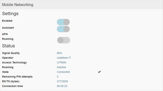
Behavior of the wireless modem can be configured from the HMI device System Setting tool:
System Settings -> Network -> Mobile Network
The Mobile Network section is available only when the optional PLCM09 module is plugged to the HMI device
Parameter
Description
Enabled
Enable the Wireless Modem
Autostart
Enable the Wireless Modem automatically when HMI device is power on
SIM PIN
SIM Card PIN code if required
APN
APN (Access Port Name)
If you do not know this information please contact your mobile services provider.
Roaming
Enable Roaming option if required
Authentication
Select the authentication mode. Could be:
Username
Password
Username and password to be used when the authentication mode is selected
Once settings has been confirmed the system under Status you can find detailed information regarding the SIM card and mobile network connection.
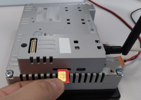
SIM Card installation
PLCM09 uses Micro-SIM SIM Card format.
Insert SIM card with chip side facing PLCM09 module front side, as shown in the below image.
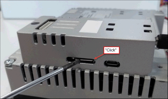
Once inserted the Micro-SIM in the apposite slot push it until you hear a “click” sound, this means that the Micro-SIM has been fully and correctly installed into the Micro-SIM slot.
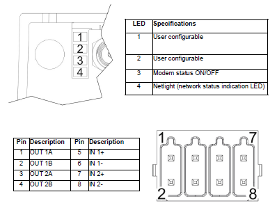
LED and Digital I/O
Behavior of the first two available LEDs and of the Digital I/O can be configured from the HMI device System Setting tool:
System Settings -> Plugins -> PLCM09
Digital I/O
Description
Input-1
Input-2
User configurable:
-None
-Cloud: 0=down, 1=up
When the input signal is on, HMI device will connect to remote cloud. When it is off, the remote cloud will be disconnected.
-Mobile: 0=down, 1=up
When the input signal is on, HMI device will start the wireless modem. When it is off, the wireless modem will be disconnected.
-1=system reboot
When the input signal is detect to be 1, HMI device will force a reboot
Output-1
Output-2
User configurable:
-None (not used)
-User controlled
Output signal will be managed by the HMI application
-Cloud: down=0, up=1
Output will be set to 1 when cloud connection is active, 0 when not active
-Mobile: down=0, up=1
Output will be set to 1 when wireless modem connection is active, 0 when not active
LED
Description
LED #1
LED #2
User configurable:
-None (not used)
-User controlled
LED status will be managed by the HMI application
-Cloud: down=off, up=on, error=blink
Show the cloud connection status
-Mobile: down=off, up=on, error=blink
Show the mobile connection status
LED #3
Show the wireless modem status:
-OFF = Disabled
-ON = Enabled
LED #4
Show the network activity (blinking)
SMART AUTOMATION APS ∙ BRANSAGERVEJ 5 ∙ DK-9490 PANDRUP ∙ DENMARK ∙ PHONE +45 7734 9960 ∙ SALG@SMARTDK.COM ∙ CVR: 31769574 ∙ WWW.SMARTDK.COM